One can 3D print with conductive filament, and therefore plausibly create passive components like resistors. But what about active components, which typically require semiconductors? Researchers at…
Well yeah, you could do that with any PTC + resistor. That is then a circuit, not an active component. Also you would likely have to use more energy than you would gain from “amplifying” since the heat would conduct away from the target and radiate away.
For example, if you had a photoresistor and used an LED to turn its resistance from high to low, that doesn’t make the photoresistor an active component.
Plus in the paper, the small wire + geometry is a prerequisite to do the resistance switch without melting everything.
They did do the thing that HewlettHackard is describing. Check out the AND gate in the linked article. The input paths are short and use small wires, but also cross the larger paths that normally link the output to ground. If both are active, the paths to ground are interrupted, and the resistor to VCC pulls up the output. So they did make logic gates. In the paper they also demonstrate NOT and OR.
I gather there’s a technical sense of “active” that’s used in electrical engineering that might not apply here, but to someone like me, with only a tinkerer’s knowledge of components, logic gates seem like enough to justify the term in the headline.
Well, a logic gate doesn’t fundamentally have to amplify… if the control current exceeds the output, it isn’t amplifying but fill performs logic. I am too lazy to look myself, but did they demonstrate amplification? If not, I think it’s doable.
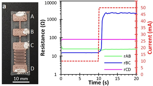
They don’t talk that much about current in particular; figure 5 only shows the resistance in the regulated output path as a function of the voltage on the control path, which isn’t enough to actually say whether there’s specifically current amplification. (Also, the gain would be negative; does that matter?) But they do discuss the fact that the output channel is much wider, which strongly suggests it’s able to pass more current (since they mention the resistivity drops as the cross-sectional area of the trace increases). The wider trace is one that wouldn’t have the fuse behavior on its own, because the resistivity is too low for it to heat up enough to trigger that at the voltages they’re using, but the close proximity of the very thin fusing wire of the control signal is enough to cause a nonlinear resistivity change in the output path as well. I think that means they’re using a single voltage for both kinds of path, and that the control current is thus lower than the output current because the resistance on the control path is higher, but I’m not certain. I am not an electrical engineer, just an enthusiastic amateur.
My quick and dirty math based on some captions of the figures from the paper suggest it’s unlikely they’re getting amplification for now, because it seems like the even the “low” resistance state is quite resistive. But I still suspect it can be done, and they do characterize their structures as “active” - thanks!

Well yeah, you could do that with any PTC + resistor. That is then a circuit, not an active component. Also you would likely have to use more energy than you would gain from “amplifying” since the heat would conduct away from the target and radiate away.
For example, if you had a photoresistor and used an LED to turn its resistance from high to low, that doesn’t make the photoresistor an active component.
Plus in the paper, the small wire + geometry is a prerequisite to do the resistance switch without melting everything.
They did do the thing that HewlettHackard is describing. Check out the AND gate in the linked article. The input paths are short and use small wires, but also cross the larger paths that normally link the output to ground. If both are active, the paths to ground are interrupted, and the resistor to VCC pulls up the output. So they did make logic gates. In the paper they also demonstrate NOT and OR.
I gather there’s a technical sense of “active” that’s used in electrical engineering that might not apply here, but to someone like me, with only a tinkerer’s knowledge of components, logic gates seem like enough to justify the term in the headline.
Well, a logic gate doesn’t fundamentally have to amplify… if the control current exceeds the output, it isn’t amplifying but fill performs logic. I am too lazy to look myself, but did they demonstrate amplification? If not, I think it’s doable.
I think so? It’s section 3.2 of the paper: https://www.tandfonline.com/doi/full/10.1080/17452759.2024.2404157#d1e604
They don’t talk that much about current in particular; figure 5 only shows the resistance in the regulated output path as a function of the voltage on the control path, which isn’t enough to actually say whether there’s specifically current amplification. (Also, the gain would be negative; does that matter?) But they do discuss the fact that the output channel is much wider, which strongly suggests it’s able to pass more current (since they mention the resistivity drops as the cross-sectional area of the trace increases). The wider trace is one that wouldn’t have the fuse behavior on its own, because the resistivity is too low for it to heat up enough to trigger that at the voltages they’re using, but the close proximity of the very thin fusing wire of the control signal is enough to cause a nonlinear resistivity change in the output path as well. I think that means they’re using a single voltage for both kinds of path, and that the control current is thus lower than the output current because the resistance on the control path is higher, but I’m not certain. I am not an electrical engineer, just an enthusiastic amateur.
My quick and dirty math based on some captions of the figures from the paper suggest it’s unlikely they’re getting amplification for now, because it seems like the even the “low” resistance state is quite resistive. But I still suspect it can be done, and they do characterize their structures as “active” - thanks!